In this guide 6 sections
Bend allowance is the length of neutral axis that a bend consumes in the flat blank. Bend deduction is the amount you subtract from the outside dimensions. K factor locates the neutral axis within the thickness. Prove each value on a test bend, then store it by material, thickness, tooling and angle.
What the three terms describe
When a sheet bends, the outer skin stretches and the inner skin compresses. Somewhere inside the thickness a layer keeps its original length. That layer is the neutral axis, and the flat blank is cut to its length.
K factor is the ratio of the neutral axis position to the sheet thickness. Bend allowance is the arc length of that axis through the bend. Bend deduction is the gap between two outside set-backs and the flat length.
The three are linked. Know one with the radius, angle and thickness, and you can work out the others. Shops pick whichever their CAD or nesting package asks for.
- K factor: neutral axis position as a ratio of thickness
- Bend allowance: arc length added for each bend
- Bend deduction: amount taken off the outside dimensions
- Inside radius: the number every formula leans on
Why a flat pattern comes out wrong by a fraction
Textbook tables assume a bend that your press brake may never make. Air bending, bottoming and coining stretch the metal differently. A table value for mild steel says nothing about your die opening.
Small errors add up. A part with six bends and a tenth of a millimetre lost at each one arrives out of tolerance at the far flange. The operator then shims, re-strikes or scraps the first off.
Grain direction, coil batch and thickness tolerance also move the result. Stainless springs back more than mild steel, so the angle you program is not the angle you get.
Prove the value on a test bend
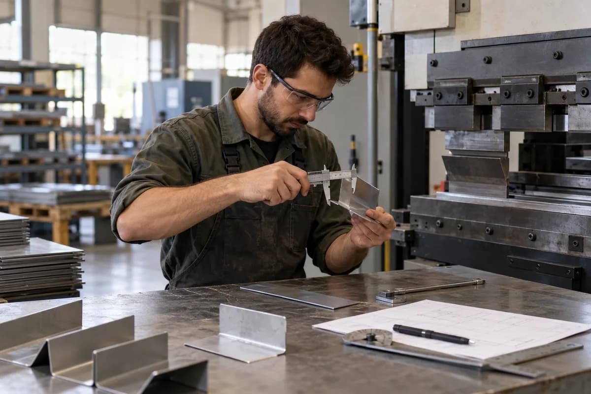
Cut a strip from the actual sheet. Bend it with the actual punch and die, then measure the flange lengths and the angle with calipers and an angle gauge. Work back to the K factor that explains what you measured.
Do this once per combination and record it. The combination is material, grade, thickness, punch radius, die opening and bend angle. Change any one of them and the proven value no longer holds.
Short note for the programmer. Never copy a value from a different tool set just because the thickness matches.
- Material grade and sheet thickness
- Punch tip radius and die opening
- Bending method: air, bottom or coin
- Measured angle and measured flange lengths
- Date, operator and machine used
Where the proven values should live
Most shops keep them in a programmer’s head, a notebook near the press brake or a spreadsheet nobody dares edit. Then the programmer leaves, and the next repeat order gets a fresh round of trial and error.
A bend table should sit with the part and tool records, so the CAM export and the job traveller both read from it. When a value is corrected after a first-off, the correction belongs in the table and not on a sticky note.
Version the table. A drawing revision, a new coil supplier or a worn punch can all justify an update, and you need to know which parts were cut under the old value.
A first step for this week
Pick your five most repeated parts. Pull the last first-off report for each and note what correction the operator made at the brake. Enter those corrections as bend table rows against the right tool set.
Next time one of those parts comes round, compare the new flat pattern with the old one. If the first piece passes without shimming, the table is working and you can extend it to the next ten parts.
Bend value record sheet
One page, one row for each proven bend. Columns cover material and grade, thickness, punch radius, die opening, bending method, target angle, measured angle, K factor, bend deduction, test date and operator. A footer block lists the drawing revision and the coil batch.
Open a blank worksheet to printQuestions owners ask
Is a K factor of 0.5 always safe to use?
No. It is a convenient default and it often gives a close flat length for thin sheet with a tight radius. Thicker plate, a wide die or stainless can sit well away from it, so measure.
Should the CAD model or the press brake own the bend values?
The shop floor result should win. CAD holds the default, the first-off proves the real value, and the proven number then feeds back into the table that CAD and CAM use.
How often do bend values need rechecking?
Recheck when tooling is reground or replaced, when the material supplier changes, or when first-offs start needing shims again. A drift in the same direction on several parts is the sign.
Can software calculate the flat pattern for me?
CAD and nesting packages do the arithmetic. They still depend on the values you feed them, so the table of proven numbers matters more than the formula.