In this guide 6 sections
Place inspection at the points where a defect becomes expensive: after honing the bore, after grinding the rod, after cutting seal grooves, after assembly and at the pressure test. Log gauge readings against the lot number at each point, so a leak found at the end leads straight to the operation that caused it.
Choose checkpoints where a defect becomes costly
Inspect after every operation you cannot undo. Honing a tube too large cannot be fixed, and a seal groove cut too deep scraps the piston before anyone has assembled anything. A finished cylinder that leaks wastes the seals, the oil and a slot in the test bay, and then the whole cylinder comes apart again.
For a cylinder the usual points are tube receipt, bore honing, rod grinding and chroming, piston and gland machining, assembly and the final pressure test. A fitting needs fewer stops, namely the turned or forged blank, thread cutting, plating and the leak check, with no bore or rod to measure.
Write the plan as a table, one row per checkpoint, with the characteristic, the gauge, the frequency and the reaction when a reading fails.
Bore, rod and surface checks
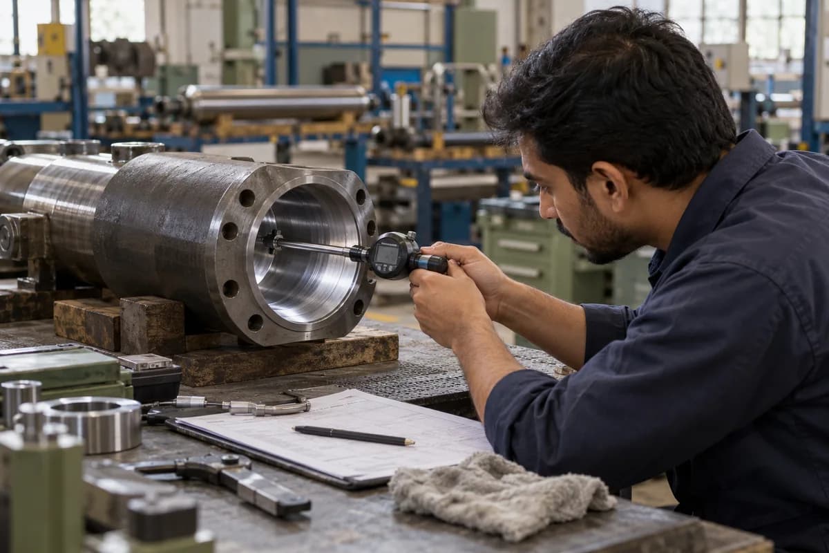
The bore decides whether the seal holds. Measure diameter with a bore gauge set from a master ring, check roundness and taper at both ends and the middle, then read surface roughness with a profilometer. Crosshatch must be even, never scored.
Rods need straightness and finish. Roll the rod on V-blocks under a dial indicator, record the runout, and check chrome thickness and roughness before the rod goes anywhere near a gland. A bent rod wears seals fast.
Record the actual reading, never just pass. Trends in those numbers show hone wear and grinding wheel wear long before any single reading falls outside tolerance on the drawing.
- Bore diameter, roundness and taper
- Bore roughness and crosshatch pattern
- Rod runout on V-blocks
- Rod chrome thickness and surface finish
- Tube wall and length against the drawing
Seal grooves, threads and ports
Seal grooves are small and unforgiving. Check groove width, depth, corner radius and floor finish because a sharp corner cuts an O-ring on assembly and a rough floor leaks past a good seal.
Threads on fittings and port connections need a go and no-go thread gauge, checked on every lot and on the first piece after any tool change. Also check the cone angle on flared and compression ends and the sealing face on face-seal types, since a bad angle leaks under pressure.
Deburr and clean before assembly. A single metal chip left in a port can score a valve spool later, so record the cleanliness check on the traveller beside the thread result.
Assembly and pressure testing
Before assembly, confirm that each seal kit matches the cylinder, because mixed-up kits are common when several bore sizes run on the same bench. Then check stroke, free movement and gland torque.
At the test bay, hold the cylinder at the specified test pressure for the stated time and watch for external leakage, drift and internal bypass across the piston. Log pressure, hold time, result and tester.
A failed test stops the lot. Pull the readings for that lot from the bore, rod and groove checkpoints and look for the shared cause, such as one worn hone or one bad tool offset.
Logging readings against the lot
Oil and bins eat paper travellers. A shared sheet or inspection module that stores the gauge reading, the gauge number and the inspector against the lot makes the history searchable.
Gauge calibration belongs in the same record. A reading taken with a gauge that expired last month is not evidence, so the calibration due date should block a reading from saving once it has passed.
Start with one product family. Build the checkpoint table for it, use it on live lots for four weeks, then see which checks never failed and which caught the most.
- Lot and serial number on every reading
- Gauge identifier and calibration due date
- Inspector and date
- Disposition: accept, rework or scrap
Hydraulic in-process inspection plan
Single-page table, a row for each checkpoint from tube receipt to pressure test. Columns give the characteristic, drawing limit, gauge used, sample size, frequency, reaction on failure and a box for the reading. A footer holds the test pressure, hold time, lot number and inspector’s signature.
Open a blank worksheet to printQuestions owners ask
How many pieces should be inspected at each checkpoint?
Inspect the first piece after setup or tool change and then a sample at a set interval. Critical characteristics such as bore size may need every piece.
Do fittings need the same plan as cylinders?
They need a shorter one. Focus on thread gauges, sealing faces, plating and a leak check, since fittings have fewer machined features.
What readings should we log numerically?
Log bore diameter, rod runout, groove depth, surface roughness and test pressure as numbers. Pass or fail is enough for visual checks.
Who signs off a failed pressure test?
The quality head decides whether the lot is reworked or scrapped, after reviewing the earlier readings for that lot.